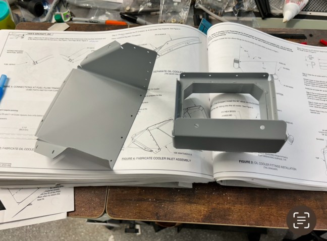
Oil Cooler

Tonight I riveted together the oil cooler inlet. I had hoped to squeeze all the rivets but the flanges made that impossible. I fired up the compressor and put my rivet gun skills into practice.

Oil Cooler

I started on the oil cooler tonight by deburring and priming the two parts that for the plenum for guiding air from the scat hose into the cooler.

Dip stick

Tonight I installed the dipstick on the engine. Just a few minutes of work to screw it into place, I still need to torque this and safety wire it, but I don’t have a big enough crow foot to complete the task.

Plastic cap removed
I used food grade anti seize per the engine manual
Screwed into position

Control cables

Today I was able to spend a few hours working on the airplane. I managed to get all of the control cables installed and routed. I appear to have a control interference issue between the pilot stick and the throttle, and looks like I need to remove half an inch off of the left control stick. However, I need to measure the amount of throw in the aileron pushrods, because it might be that the stick can’t actually move that far horizontally before the bell crank hits its limit.

I was able to connect the prop and alternate air controls, and the mixture and throttle connected. I can’t connect the heat flap actuator until I finish drilling some holes in the bottom cowling.

The routing through the wiring under the panel worked out ok. The prop control was just barely long enough, but I think it’ll work ok. I have loosely connected it for now to ensure I have the right length and throw on the lever. The alt air works great, and the mod from aircraft specialties, allowing the door to open and close, is a nice upgrade.

Controls
Controls
Throttle cushion gap. This is a larger gap than is called for, but I can’t get anything less than this without it being too small of a gap
Behind the control bracket
Under the panel. In the top right you can see the somewhat messy routing of control cables through (actually above) the wiring bundles
Heat flap control
Throttle cable attach. Blue tape indicating this is not final torqued
Mixture control
Throttle and mixture controls

Control Cable Bracket

Tonight I started working on the control cables. Vans sent me the correct control cable bracket, which has an extra hole for the cooling flap, and a redesigned layout. It’s made from slightly thicker material and feels solid. I was able to prime it yesterday, so I mounted it tonight. I also trimmed the alt air cable and the cooling flap cable. The cooling flap cable has a push-button release mechanism, which uses a small ball bearing to create the friction necessary to hold the cable in whatever position it’s set. The instructions have you pull the knob out 6 inches, then cut the end of the cable. At about 5 inches, the ball bearing is exposed and falls out if you aren’t careful. I noticed this and put the parts into a zip lock bag while I trimmed the cable, then reinstalled it. It would be a major pain in the butt if the ball bearing fell out onto the floor, I would never find it!

The cabling under the panel is going to present a challenge for routing these control cables, but I plan to pass each cable between the cable bundles and the mounting frame I built forward of the sub panel. It should work ok, although I’m sure I’ll run into some kind of challenge.

Original bracket on the left, new one on the right
The cooling flap control. Barely visible is the small hole where the ball bearing sits, just above the “2” on the ruler.
The ball bearing, spring, and button which forms the grip mechanism inside the cooling flap control cable handle.

Engine Sensor Wiring

Tonight I wired up the Manifold Pressure, engine oil temperature, and fuel pressure sensors. I wanted to finish the job and wire up the oil pressure sensor, but I ran out of butt splices. I tested the sensors by powering up the instrument panel and looking for signals. I was happy to see all of the gauges reporting data correctly.

I also took the opportunity to test and adjust the canopy unsafe warning. At first the canopy pins weren’t contacting the micro switch, but after a quick adjustment it now works great.

Oil temperature sensor wiring
Typical connection between sensor and wiring harness. I used butt splices because I don’t want these to come apart in-flight, and I have plenty of wire length to allow cutting and re-doing this if I even need to replace the sensor

Heat vent controls

Tonight I installed the two heat vent cockpit controls. These are push/pull controls that are mounted on the instrument panel and open the heat vents, one pilot side, and one passenger side.

No real challenges installing these controls. I was careful to ensure I had a 1/16 cushion gap when the vents are fully closed. This will be more critical on the other controls, but it was good practice.

In the process of reading through the plans I made a couple of realizations. One is that I have the wrong version of the control mounting bracket. The version I have is labeled as the updated part number with a -1 at the end, but it’s actually the old version. I emailed Vans to confirm, hopefully I can get a new one quickly. I could just make a new one, but locating the holes would be time consuming. Unfortunately I’m blocked on the rest of the control cable install steps until I have that bracket in-hand.

The other realization is that my panel wiring harnesses are going to be interfering with the control cables. I can probably make it work, but will need to look out for chaffing problems in places where the wiring bundles and control cables are touching.

The control cable collection
Pilot side cabin heat control
Passenger side heat control
The mechanism to open and close the heat vent. These are on the firewall.
Routing of the control cable

Oil cooler

After a 10 day work trip to India I was able to accomplish one small task tonight. I cut and deburred these spacers for the oil cooler. Right now this is about all I’m going to do with the oil cooler. I’m hoping to pick up a 3D printed oil cooler plenum to replace the standard Vans model. The 3D printed plenum will be circular to match the circular scat tube, vs. the square cornered Vans model. Based on what I’ve read and been told, there should be some improvement in oil cooling efficiency using this modified plenum. It’s currently in testing and not ready for production, but hopefully will be ready near the end of the year.

I also took a few minutes to confirm that my oil cooler serial number is not in the range impacted by the service bulletin issued earlier this year. https://www.vansaircraft.com/service-information-and-revisions/sb-00080-rev-2/

Oil cooler spacers

Manifold pressure line

Tonight I installed the cushion clamps to secure the manifold pressure line, and the rubber hoses to route pressure to the e-mags.

I found I had to make an adjustment to the routing of the line, so I removed the engine-side connector, rerouted, then reconnected the line. That also led to moving some clamps around, but I think I have a good routing now. Once the oil cooler scat tubing is installed I may have some interference, but I’ll deal with that later.

Installing the rubber tubes was kind of a pain, as access to the mags is somewhat restricted. But I get the feeling it will be even worse when I have to do some wiring back there.

Rerouted line to work around the engine mount
The rubber hoses installed
Final routing on the left hand side

Oil Pressure and Manifold Pressure

Tonight I installed the oil pressure sensor line, and started on another modification to move the manifold pressure sensor. This modification is courtesy of Steve at Aircraft Specialties and makes use of the unused port on the Vans bracket. It’s a more elegant solution for providing manifold pressure to the two E-mags, in my opinion.

The oil pressure line was straight forward, just connecting two fittings with a hose, and torquing the b-nuts.

The manifold pressure line was slightly more involved. First uninstalled the pressure sensor from its original location on the right side of the firewall, and reinstalled it on the left side, using the spare port. I hunted around and found a spare plug, and then installed that along with the Aircraft Specialties supplied fluid fitting. I made up the rest of the fittings, routed the lines across the engine compartment and installed the line at both ends. Now I just have to locate and install the cushion clamps to secure it in place.

Oil pressure line connected and torqued
Manifold pressure line routed across the top of the engine compartment. The two needle fittings will connect to the two e-mags using lengths of rubber hose
The lines routing to the Vans bracket
Top-down view of the Vans bracket. The fitting on the right is a straight fluid fitting, despite looking like it’s 45 degrees in this picture. Sensors from left to right: oil pressure, fuel pressure, manifold pressure