Oil Cooler Install

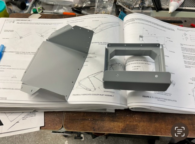
Today I worked on installing the oil cooler. I was able to get it done, but I did run into some problems. The biggest issue was that the plans called for a 60 degree clocking of one of the fluid fittings on the oil cooler. But this angle had it pointed directly at the scat tubing for the cabin heat. There was no way the oil line would have fit, and access to the fitting was limited. Unfortunately I didn’t realize this issue until I had already set the RTV and installed the air inlet. My choices were to either remove the oil cooler and the fluid fitting then reinstall at a different angle, or move the scat hose out of the way. I decided to try to move the scat hose and the related assembly to make room for the oil line. This seemed less disruptive than removing the oil cooler and redoing the RTV.

In the end I was able to move the scat hose just a little, and while it was disconnected I hooked up the oil line. Once the oil line was routed to the engine, it bent away from the scat hose just enough to make it work out.

Torquing the b-nuts on the fluid fittings was challenging, as I had to use a crow foot to apply torque. I used a wrench to hold the fluid fittings while torquing the b-nuts to avoid applying excessive torque to the oil cooler.

In the end I’m pretty happy with how it turned out.

The air inlet. The large bead of red RTV in the foreground squeezed out once I torqued the bolts. It was subsequently removed leaving that row of veins unobstructed.
The fluid fitting in the top of the picture is oriented to be pointed directly at the scat tube. I had to move the scat tube out of the way to allow the oil line to fit
Looking up after moving the scat tube. The fluid fitting is visible in the background, just to the right of the scat tube. This was enough to allow the oil line to sneak past the scat tube.
The oil line connected and torqued
The other oil line connected and torqued
One of the oil lines where it connects to the engine. In the background is a rats nest of wiring, something I’m looking forward to tidying up soon.
Looking down, both oil lines are visible, either side of the oil filter. The red cap in the foreground is the last port that needs a fitting. This is an unused tach port, and I need to order a cap to go over it.

Oil Cooler Fittings and Seals

Tonight I installed the two fluid fittings on the oil cooler, and the two rubber seals which will sit between the oil cooler and the air inlet.

The fluid fittings were easy enough. Vans published a video of this procedure, highlighting the need to use two wrenches to avoid torquing (and cracking) the oil cooler. The cooler is made of fairly soft aluminum, and cannot handle the torque needed to seat the fluid fittings. There have been cases of oil coolers failing in flight, and even a recall on a batch of coolers (mine is not affected).

I followed the video, measured the clocking angle, and installed the two fittings.

Then I proceeded to apply silicone adhesive to the sides of the top of the cooler, and followed the instructions to glue down the two seals.

I also spent time filling in the remaining gaps on the inlet where I missed a spot or two when applying RTV last night.

Oil cooler
Installing the first fluid fittings
Both fittings installed. Note the two wrenches used, one to hold the nut on the cooler, and one to torque the fitting
Beds of silicone adhesive applied
Seals glued down
Close up of the left hand seal

Oil Cooler

Tonight I riveted together the oil cooler inlet. I had hoped to squeeze all the rivets but the flanges made that impossible. I fired up the compressor and put my rivet gun skills into practice.

Oil Cooler

I started on the oil cooler tonight by deburring and priming the two parts that for the plenum for guiding air from the scat hose into the cooler.

Oil cooler

After a 10 day work trip to India I was able to accomplish one small task tonight. I cut and deburred these spacers for the oil cooler. Right now this is about all I’m going to do with the oil cooler. I’m hoping to pick up a 3D printed oil cooler plenum to replace the standard Vans model. The 3D printed plenum will be circular to match the circular scat tube, vs. the square cornered Vans model. Based on what I’ve read and been told, there should be some improvement in oil cooling efficiency using this modified plenum. It’s currently in testing and not ready for production, but hopefully will be ready near the end of the year.

I also took a few minutes to confirm that my oil cooler serial number is not in the range impacted by the service bulletin issued earlier this year. https://www.vansaircraft.com/service-information-and-revisions/sb-00080-rev-2/

Oil cooler spacers