E-Mag Wiring

Last night and today I worked on wiring the E-Mag electronic ignition system. The wiring was straightforward, I just followed the installation manual and connected the wires to the plugs, then installed the plugs into the magnetos. The time consuming part was routing the wires, and figuring out where to ground the mags. I ended up using the accessory pad studs as the ground, because items nearby, has easy access, and I’m not planning to install a backup alternator at this stage.

I made the ground wires, routed them, then routed the other wires (power, switch, and tach reading). Once I was happy with the wiring, I trimmed the wires, labeled them, and then installed them into the plug.

The E-Mag magneto uses electronics to time the spark, vs. just a static timing as a traditional mag does. The advantage is that the spark timing can be dynamically adjusted based on manifold pressure (which is determined by throttle position and altitude), for a more efficient fuel burn.

The original electronic magnetos needed a backup power supply to continue to operate in an electrical failure scenario. This model has a built in alternator in each magneto, so it will keep running even if all power is lost, and/or manifold pressure is lost. That makes it way simpler to install, and more reliable.

The wiring includes a power wire to power the electronics from the electrical bus, a switch wire to immobilize the unit when activated, and a complimentary tach output which serves as a tech reading for the Garmin system, then there is a ground wire for local ground to the engine block.

The two ignition switches on the panel each have an “off”, “on” and “test” position. They control the left and right magnetos independently. When “off” the switch grounds the “kill” (lt/rt mag sw) wire, which immobilizes the unit. In that condition it is still “awake” and drawing power from the electrical bus, as long as the battery switch is activated. When the ignition switch is set to “on” the kill wire is ungrounded and the ignition will fire. When set to “test”, the power wire is disconnected. The test is to ensure the unit’s internal alternator runs and provides power to the unit. One important note: the internal power has a minimum RPM setting, something around 1100 RPM, below which the internal power will not function. This has several important implications:

  • The engine can’t be started without external (to the E-Mag) power.
  • The “test” function before flight should be performed above 1100 RPM, ideally at 1700 RPM. The engine RPM will drop if a magneto is in “test” and RPM is below 1100. The engine will quit if both magnetos are in “test” and RPM is below 1100.
  • In an emergency if the battery buss is no longer supplying electrical power, and the engine were to quit for any reason, a restart is only possible if the prop is windmilling above 1100 RPM. An example of this condition could be an alternator failure, followed by a fuel starvation event. If switching tanks were to remedy the fuel starvation, the prop needs to be >1100 RPM for the magnetos to fire.
Left hand magneto plug.
Left hand magneto plug, with some heatshrink applied
Plug secured into the magneto. The wiring runs through an adel clamp for support, then to the firewall through the sleeve in the foreground
Right hand magneto plug
Right hand plug installed. Here you can see the adel clamp, the wiring sleeve, and the two ground wires attached to the accessory pad in the top left. The right hand magneto is oriented so that the plug is on the top side, and the left had magneto has the plug facing down. Apparently this is configurable, but Lycoming set it up this way and I don’t see a reason to change it.

Firewall Forward Wiring

The last few evenings I’ve been working on finalizing the wiring runs in the engine compartment. I looked at a few other aircraft blogs to get a few ideas, and ordered a few supplies. I started by working on the ignition leads and the EGT and CHT probe wiring. I switched out some of the adel clamps I had been using and went with -6 size clamps for all the ignition leads. The leads are slightly loose in this size clamp, but the -5 size is too tight. I wanted to be able to run zip ties through some of the clamps, and it’s helpful to have a little bit of play. The silicone cover on the leads sticks very well to the cushion clamps, so the -6 size seems to work well.

I also used some short (1/4 inch) lengths of rubber tube to create stand-off spacers for the wiring. Running zip ties around the wire bundles and through the tube keeps the wiring together but separated by 1/4 or 1/2 inch or so. Apparently it’s a good idea to have some spacing between the ignition wires and the other wiring runs to minimize interference.

Installing adel clamps is a pain, even with the clamping tool and using safety wire to hold the clamps shut. It’s just slow going.

It’s also slow going trying to visualize the wiring runs, and trying to figure out what wiring will go where. I had to redo work a couple of times, and can already tell I’ll be redoing things in the future. It feels like an iterative process to get everything worked out and squared away.
I’m using a fireproof abrasion protection sleeve on almost all of the wiring. This helps keep the wiring neat and tidy and I hope it will keep it cleaner. The sleeve can be slipped on around the wiring which makes it much easier to install and remove.

Right hand side of the engine
Aft-right corner of the engine. I used some spiral wrap in places where wires and tubes come into contact
Aft-right corner. The CHT and EGT wiring is contained inside the black sleeve the hangs below the red ignition lines
Left hand side wiring. This has the added complexity of the alt-air control cable running through the area

Misc Firewall Forward

Tonight I tackled a few small jobs that had been on the to-do list. I switched out the manifold pressure fluid fitting for one with a restrictor inside, I took some adel clamps off and reinstalled for better wire routing, I safety wired the oil dipstick mount, and I plugged the e-mag ignition cables into the spark plugs.

The manifold pressure fitting I had installed was the Vans component I had originally installed. I later bought the Aircraft Specialty emag install kit, which comes with a 45 degree fitting with a flow restrictor inside. The flow restrictor dampens the fluctuations of air pressure when the engine is running, making for a more accurate manifold pressure reading.

To replace the fitting I first took off the air line, and tried to access the fitting. The baffling makes access a little difficult, so I decided to disconnect the oil return line so I could move that out of the way to gain access. I was then able to access the fitting and remove it. I cleaned up the threads, and then installed the new 45 degree fitting (used loctite 567). Unfortunately I could rotate the 45 degree fitting due to interference with the fluid fitting for the oil return line. I ended up removing that fitting too, installing the MP fitting, cleaning the threads, and then reinstalling the oil return fitting and then the line itself. It was a bit more work than I hoped, but it turned out well and the new setup is much better. The 45 degree fitting also allowed me to reroute the MP line to a more convenient location, out of the way of the oil cooler scat hose.

Safety wiring the oil dipstick mount was hard to reach, but not too bad once I had figured out how to get my hands into the small gap.

I plugged in the ignition lines, and started working on changes to the clamp setup to hold the lines.

The stainless line is the manifold pressure sensor line. This now connects to the back right cylinder via a black 45 degree fluid fitting. The blue fluid fittings are the oil return line which I had to disconnect to gain access to the MP fluid fitting
Safety wired oil dipstick mount
Two of the ignition wires I connected. I need these connected so I can finalize my wire routing in the engine compartment

Cooling Flap

With the oil cooler in place, and the cowling holes drilled, I was able to final install the cooling flap, and hook up the control cable.

I found the screws and mounted the cooling flap assembly to the bottom of the fuselage. In the process I noticed a series of 4 pre-drilled holes in the bottom of the fuselage that I’ll need to investigate and probably fill. Two of them look like a spare antenna mount, and the other two could be drain holes.

Once the flap was in position I hooked up the control. It was a little fiddly to get it just right, but in the end it worked out ok. The flap closes and leaves a small cushion gap per the plans, and it operates very smoothly.

After I finished I noticed that the plans call for washes under the screws that hold the cooling flap in position. They aren’t mentioned earlier in the plans when initially test fitting the cooling flap assembly, so I hadn’t noticed them at first. I’ll have to find the washes and install them later.

Cooling flap assembly installed and taped down at the back end
Threading the control cable through the drilled bolt that acts as the pivot point for the flap door control
Cushion gap on the control
Control fully retarded to open the flap
Flap fully deployed
End of the cable after setting the length and bending and trimming the control cable
Safety wire over this clamp

Oil Cooler Install

Today I worked on installing the oil cooler. I was able to get it done, but I did run into some problems. The biggest issue was that the plans called for a 60 degree clocking of one of the fluid fittings on the oil cooler. But this angle had it pointed directly at the scat tubing for the cabin heat. There was no way the oil line would have fit, and access to the fitting was limited. Unfortunately I didn’t realize this issue until I had already set the RTV and installed the air inlet. My choices were to either remove the oil cooler and the fluid fitting then reinstall at a different angle, or move the scat hose out of the way. I decided to try to move the scat hose and the related assembly to make room for the oil line. This seemed less disruptive than removing the oil cooler and redoing the RTV.

In the end I was able to move the scat hose just a little, and while it was disconnected I hooked up the oil line. Once the oil line was routed to the engine, it bent away from the scat hose just enough to make it work out.

Torquing the b-nuts on the fluid fittings was challenging, as I had to use a crow foot to apply torque. I used a wrench to hold the fluid fittings while torquing the b-nuts to avoid applying excessive torque to the oil cooler.

In the end I’m pretty happy with how it turned out.

The air inlet. The large bead of red RTV in the foreground squeezed out once I torqued the bolts. It was subsequently removed leaving that row of veins unobstructed.
The fluid fitting in the top of the picture is oriented to be pointed directly at the scat tube. I had to move the scat tube out of the way to allow the oil line to fit
Looking up after moving the scat tube. The fluid fitting is visible in the background, just to the right of the scat tube. This was enough to allow the oil line to sneak past the scat tube.
The oil line connected and torqued
The other oil line connected and torqued
One of the oil lines where it connects to the engine. In the background is a rats nest of wiring, something I’m looking forward to tidying up soon.
Looking down, both oil lines are visible, either side of the oil filter. The red cap in the foreground is the last port that needs a fitting. This is an unused tach port, and I need to order a cap to go over it.

Oil Cooler Fittings and Seals

Tonight I installed the two fluid fittings on the oil cooler, and the two rubber seals which will sit between the oil cooler and the air inlet.

The fluid fittings were easy enough. Vans published a video of this procedure, highlighting the need to use two wrenches to avoid torquing (and cracking) the oil cooler. The cooler is made of fairly soft aluminum, and cannot handle the torque needed to seat the fluid fittings. There have been cases of oil coolers failing in flight, and even a recall on a batch of coolers (mine is not affected).

I followed the video, measured the clocking angle, and installed the two fittings.

Then I proceeded to apply silicone adhesive to the sides of the top of the cooler, and followed the instructions to glue down the two seals.

I also spent time filling in the remaining gaps on the inlet where I missed a spot or two when applying RTV last night.

Oil cooler
Installing the first fluid fittings
Both fittings installed. Note the two wrenches used, one to hold the nut on the cooler, and one to torque the fitting
Beds of silicone adhesive applied
Seals glued down
Close up of the left hand seal

Bottom Cowl Screws

Tonight I finished a job on the cowling, locating and drilling the screw attach points on the trailing edge. There are a total of 8 holes, 4 in the middle section, and two more on each side. There’s a template supplied for the outboard holes, so I made the template and drilled those outboard holes, then attached the heat flap to locate the 4 center holes.

I was careful to not drill into the nut plates, which would cause them to lose their ability to hold the screws.

Making the template. Simple cutting a part into two and using one half
Template taped into position.
Template taped into position
Heat flap temporarily installed overlapping the cowling. This gave me the locations for the 4 holes in the cowling. When finally installed, the heat flap goes under the cowling.

Oil Cooler

Tonight I riveted together the oil cooler inlet. I had hoped to squeeze all the rivets but the flanges made that impossible. I fired up the compressor and put my rivet gun skills into practice.

Oil Cooler

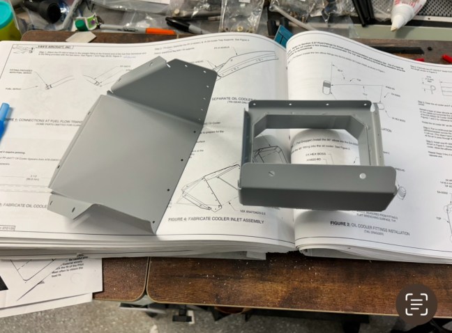
I started on the oil cooler tonight by deburring and priming the two parts that for the plenum for guiding air from the scat hose into the cooler.

Dip stick

Tonight I installed the dipstick on the engine. Just a few minutes of work to screw it into place, I still need to torque this and safety wire it, but I don’t have a big enough crow foot to complete the task.

Plastic cap removed
I used food grade anti seize per the engine manual
Screwed into position